Since the transom construction was not initially planned from the beginning we had to manipulate the last station, number 15, where the aft-most end is for the hull. We calculated how thick the fibreglass with resin on the 8mm foam to adjust the 15th frame for'ard that dimension. Then I checked the shape of the transom while the others made a pattern out of cardboard I made when making the transom flange on the hull. It was recycling but it was accurate enough to get a good shape, exactly the contour of the hull.
There did pose one more problem however, as the transom attached almost reached the floor so the floorboards holding the stations to the concrete had to be cut back allowing the transom to fit the decks aft face. Another issue was that now station 15 had moved it no longer conformed to the correct shape and required some sanding to get it to fit correctly.

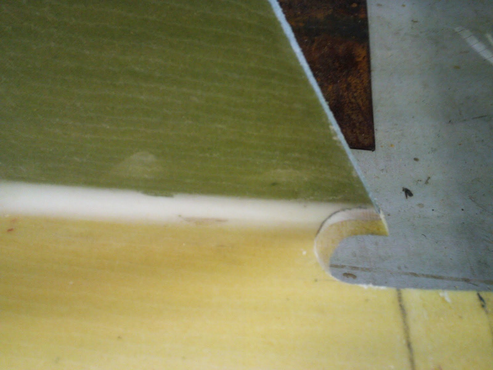
The next stage of the transom construction was the addition of the glass plate, used for the rudder and tiller to attach. The bachelor students made the glass plate out of many layers of 400g/m2 double bias fibreglass matt, making an incredibly strong and workable material for areas where high load bearing metal plate and fastenings attach. Cutting the foam away from the layer of glass using router and hacksaw blade attached to a piece of wood made a whole perfectly thick enough for the glass plate, which goes through the deck and out the other side.


A rebate of 40mm width was sanded at the edge of all the faces on the transom and sheer deckline where the fibreglass will overlap. Unfortunately resin was spilled all over the transom making it impossible for the vac tape to adhere to. Drastic measures were taken in attempting to create a seal, alas it never worked entirely. We tried to make a seal to station 15 and found air was coming through between the transom and the station! This took heaps of time trying to block this passage, it was a mess and I couldn't help thinking that (no-name) should have been careful pouring the resin over the transom, I was quite mad inside.
For details on fibre-glassing the transom see "Vacuum bagging, stacking and epoxy" http://bennifacta.blogspot.com/2011/07/vacuum-bagging-stacking-and-epoxy.html


Coved in with peel-ply to keep it tidy. A neat trick to getting epoxy in corners to cove is the e-pastry bag, which is just that, a plastic bag with the corner snipped off and filled with epoxy filler. A nice bead of filler comes out the end resulting in a much tidier job.
I cut this out using a holesaw or bore drill-bit. This is the inside of the deck's topside. I planned to have it neatly fit on top of the flange yet we found there was still some work to fair the topsides allowing the cockpit to sit exactly on the hull. We ended up with about a 2mm gap between however the flange was more than adequate to sit the cockpit on and it simply required filling with an ADR and 403 blend. It was nice to see the boat in one piece.
No comments:
Post a Comment